In-Depth
Step-by-Step: Configuring Amazon EC2 for Business-Critical Applications, Part 2
Now that you've prepared your AWS virtual private cloud, instances and storage, it's time to install and configure a SQL Server 2019 failover cluster instance.
- By Dave Bermingham
- 06/29/2021
Part 1 of this series detailed the steps required to prepare the Amazon Elastic Compute Cloud (EC2) infrastructure to support a Windows Server Failover Cluster (WSFC) that spans availability zones (AZs). Preparing the virtual private cloud (VPC), instances and storage, as well as enabling the core WSFC components, were all covered in detail.
In this article, we'll pick up where we left off and continue with the installation and configuration of a SQL Server 2019 failover cluster instance (FCI).
Choosing the Cluster Storage
A SQL Server FCI typically requires some sort of shared storage device. A SQL Server FCI built on-premises will typically store its data on a SAN. All the cluster nodes share access to the same LUN on the SAN and WSFC controls access to this shared storage through SCSI 3 reservations, ensuring only the active cluster node has access to the storage. When a failover occurs, WSFC ensures that the new node coming online gains access to the storage and all the remaining nodes are locked out.
With Windows Server 2012 and SQL Server 2012, a new option for SQL Server FCI storage was added. SMB 3 was introduced in Windows Server 2012 and it included SMB Transparent Failover along with significant performance enhancements. These new features allowed SMB file servers to be used as another possible alternative for SQL Server FCI storage.
In addition to SAN and SMB shares, third-party software solutions such as SIOS DataKeeper Cluster Edition (which is what I used in Part 1) allow users to build SANless clusters that, instead, leverage block-level replication to keep the cluster data in sync between the cluster nodes. Eliminating the need for a SAN allows you to create cluster configurations that use locally attached storage. This opens up the possibility of creating a cluster that spans geographic locations. Instead of controlling SCSI reservations, the SANless cluster solution controls the replication direction, ensuring the active cluster node is always the source of the replication and that the remaining nodes are the target(s).
As you learned in Part 1, in order to qualify for Amazon Web Services' 99.99 percent availability SLA for your compute resources, you must create a cluster that spans AZs. In this example, to meet a 99.99 percent application availability SLA, we will use Amazon FSx -- basically a hosted SMB 3 service that you can use to store your cluster data -- and SIOS DataKeeper Cluster Edition. Amazon FSx has a 99.9 percent availability guarantee, which becomes the SLA of your entire cluster.
Configuring the Cluster Storage
Launch the DataKeeper UI on either of the cluster nodes and create your DataKeeper Volume Resource as shown below.
 Figure 1
Connect to both servers -- first SQL1, then SQL2. If you have connected to both servers and the storage is configured properly, the Server Overview Report should look something like this.
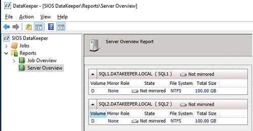 [Click on image for larger view.] Figure 2
Click Create Job to start the Job Creation Wizard.
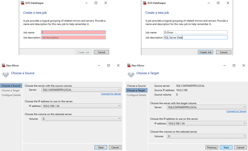 [Click on image for larger view.] Figure 3
DataKeeper supports both synchronous and asynchronous replication. For replication between AZs in the same region, choose synchronous. If you want to replicate across regions or even across cloud providers, choose asynchronous. Click "Yes" in the prompt below to register the DataKeeper Volume resource in Available Storage in the cluster.
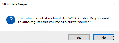 Figure 4
The DataKeeper Volume D now appears in Failover Cluster Manager under Available Storage.
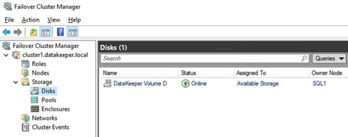 [Click on image for larger view.] Figure 5
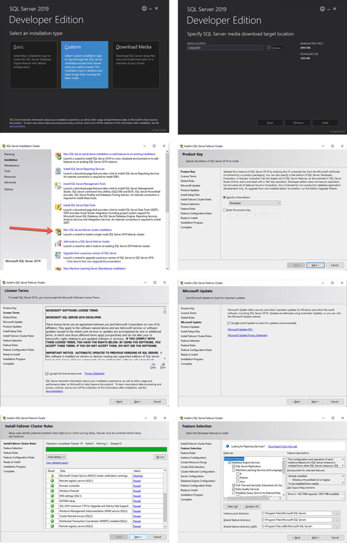
Install the First Node of SQL Server FCI on SQL1
Now that the core cluster has been created and the DataKeeper volume resource is in Available Storage, it is time to install SQL Server on the first cluster node. As mentioned earlier, the example here illustrates a cluster configuration using SQL Server 2019 and Windows Server 2019, but all the steps described in this example are virtually identical, regardless of which version of Windows Server or SQL Server you are trying to deploy.
Follow the example below to install SQL Server on SQL1.
 [Click on image for larger view.] Figure 6
The name you specify below is the client access point. This is the name your application servers will use when they want to connect to the SQL Server FCI.
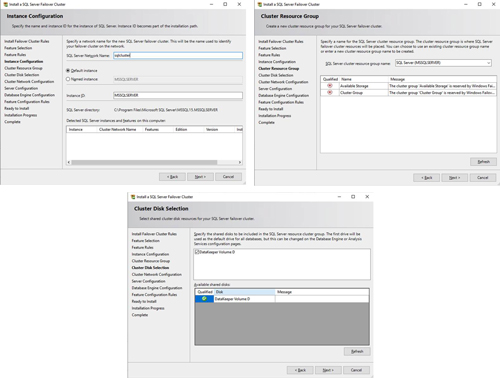 [Click on image for larger view.] Figure 7
On this screen, you will add the SQL1 secondary IP address we identified earlier in the planning section of Part 1 of this series.
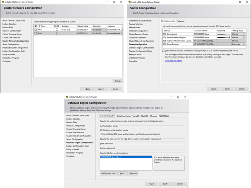 [Click on image for larger view.] Figure 8
In this example, we left tempdb on the D drive. However, for best performance, it is recommended that you locate tempdb on a nonreplicated volume or even the local instance storage.
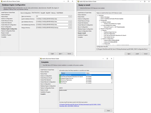 [Click on image for larger view.] Figure 9
Install the Second Node of SQL Server FCI on SQL2
It is now time to install SQL Server on SQL2. Follow the steps illustrated below.
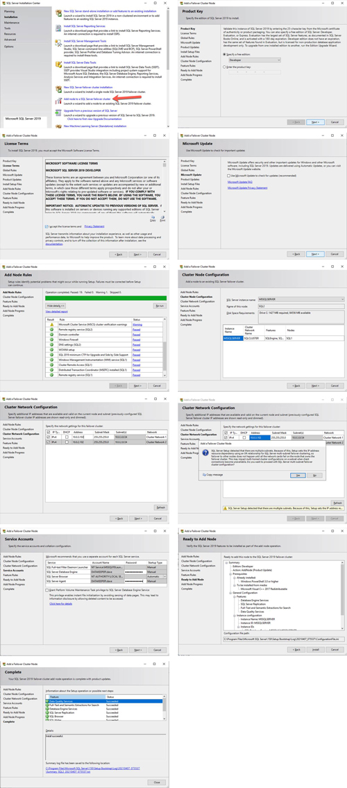 [Click on image for larger view.] Figure 10
Once you have installed SQL Server on both cluster nodes, Failover Cluster Manager should look like this.
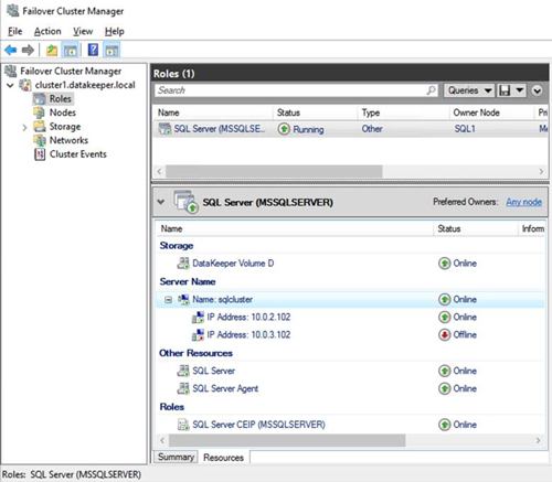 [Click on image for larger view.] Figure 11
Install SQL Server Management Studio
On SQL Server versions 2016 and later, you must download and install SQL Server Management Studio (SSMS) as a separate option, as shown below. Note: In earlier versions of SQL Server, SSMS was an option that you could choose to install during the SQL installation.
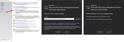 [Click on image for larger view.] Figure 12
Once SSMS installs, connect to the cluster via the client access point. Your SQL Server FCI should look like this.
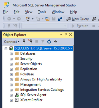 Figure 13
Multi-Subnet Considerations
One of the biggest considerations for running a SQL Server FCI in Amazon EC2 is the fact that the cluster nodes reside in different subnets. Microsoft started to account for the fact that cluster nodes might reside in different subnets by adding the "OR" functionality in Windows Server 2008 R2, as described in the Microsoft documentation.
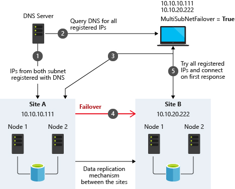 Figure 14. Source: SQL Server Multi-Subnet Clustering (SQL Server), Microsoft
The important thing described in the documentation is the concept of the RegisterAllProvidersIP on the network name resource, which is enabled by default when you create a SQL Server FCI. As described, when this is enabled, two A records will be registered in DNS with the network name resource, one for each IP address.
Using the "OR" functionality, only the IP address associated with the active subnet will ever be online and the other one will be shown as offline. If your client supports adding multisubnetfailover=true to the connection string, then both IP addresses will be tried at the same time and the client will automatically connect to the active node. That is the easiest and the default method of client redirection in a multi-subnet cluster.
The documentation goes on to say that if your client does NOT support the multisubnetfailover=true functionality, that you should "try to adjust the connection timeout in the client connection string by 21 seconds for each additional IP address. This ensures that the client's reconnection attempt does not timeout before it is able to cycle through all IP addresses in your multi-subnet FCI."
Disabling RegisterAllProvidersIP is another option that will work. By disabling the RegisterAllProvidersIP, you will only have a single A record in DNS. The DNS A record will be updated each time the cluster fails over with the active cluster IP address associated with the name resource.
The downside of this scenario configuration is that your clients will cache the old IP address until the time to live (TTL) expires. To minimize the delay in reconnection, it is recommended that you change the TTL on the name resource. This process is described here and an example is shown below that sets the TTL to five minutes
Get-ClusterResource -Name sqlcluster | Set-ClusterParameter -Name HostRecordTTL -Value 300
Keep in mind that it also may take some time for the changes to your Active Directory-integrated DNS server to propagate across your entire forest. Another option that I have seen people use is leveraging an AWS classic load balancer to redirect client connections to the active node. It is beyond the scope of this document to go into the details of this configuration, but basically you set up an AWS classic load balancer and add SQL1 and SQL2 to the back-end pool. Configure a health probe to probe TCP port 1433, or whatever port you have SQL Server configured to listen to. At that point, the load balancer knows which node is active and as clients connect to the load balancer, the load balancer redirects the client to the active node.
Summary
I wrote this article with enough detail to get you past the common hurdles that I see people struggle with on a regular basis. If you have any questions or need further clarification, leave a comment here or reach me on Twitter (@daveberm) and I'll be glad to assist.